Building a battery-powered wireless sensor using Bluetooth Low-Energy (BLE) and Apple HomeKit (Part 2)
This is the second post in a series about building a simple wireless temperature and humidity sensor using inexpensive components, Bluetooth Low Energy (BLE) for communication, and Apple HomeKit to read sensor values. For the first post, see Part 1.
In the previous post, we covered the motivation for this project and considered a few high-level designs, choosing the one that seemed best. Now that we have the main high-level design questions out of the way, let’s get into implementation details.
Hardware selection
Our sensor setup consists of 2 main modules:
- The sensor itself, to be located where temperature and humidity are to be measured.
- An HAP bridge, to be located somewhere within communication range of the sensor (up to ~100m).
Let’s take a closer look at the hardware components comprising each of these modules.
Sensor
The sensor module has 2 main hardware components:
- BLE SoC (System-on-a-chip) – for managing bluetooth communication
- Temperature/Humidity sensor – for (you guessed it!) sensing temperature and humidity
BLE SoC
In the first post of this series, I explained that I had chosen the Nordic Semiconductor nRF52832. This is one amazing little chip – it packs considerable processing power, with extremely low power requirements, and at a low cost. Here are some of its key specs:
- 32-bit ARM Cortex-M4F Processor @ 64MHz
- 1.7v to 3.6v operation
- 512kB flash + 64kB RAM
- 96dBm sensitivity
The nRF52 is available as an IC only for an easy $2.50 a piece in a flat no-leads package, but for prototyping purposes, you’ll want to work with a breakout board. There are a bunch of nRF52 prototyping boards on the market, including the ones below:
| Manufacturer | Model | Price |
|---|---|---|
| SparkFun | WRL-13990 | $19.95 |
| RedBear | BLE Nano v2 | $16.90 |
| Nordic | nRF52 DK (development kit) | $39.00 |
I chose the SparkFun WRL-13990, for a few reasons:
- It has solid, easy-to-read documentation
- It comes pre-programmed with a serial bootloader. That means that it can be programmed using a simple USB-to-serial converter instead of a more complex and expensive JTAG programmer. It also has its pins arranged so that it can be easily attached to such a USB-to-serial programmer.
- It’s compatible with the Arduino IDE. This adds the huge benefit that existing Arduino libraries and samples can run on the chip.
- It’s relatively inexpensive
- It has LEDs and buttons for easy debugging
- It has a small form factor (especially in comparison to the nRF52 DK)
I predicted that programming the nRF5 would be one of the most challenging parts of the project, and I chose the WRL-13990 in hopes that it would greatly simplify this process.
One important note about the WRL-13990 is that it comes without headers attached. In order to use it in this project, the headers need to be soldered on, which requires basic soldering tools and skills. If this is a dealbreaker for you, you might want to consider another board instead.
Temperature/Humidity sensor
I chose a DHT-22 temperature/humidity sensor because it has extremely wide support, discussion, and documentation within the Arduino community. I chose it over the lower-cost DHT-11 because of its higher sensor-reading precision.
USB-to-serial programmer
Although strictly speaking it’s not part of the sensor, a USB-to-serial (sometimes called USB-to-TTL) programmer chip is needed to program software into the nRF52. USB-to-serial chips are very cheap and easily available, with a few ICs forming the core of different PCB variations in the market. I chose an FTDI FT232RL-based board that I found listed on eBay for a few dollars.
HAP bridge
For the bridge, we have the following basic requirements:
- Capable of BLE communication
- Capable of Wi-Fi communication
- Capable of running the node.js-based bridge server software
- Low power requirements (preferably)
Our computational resource requirements are very low, since the bridge will only serve to periodically relay readings from the sensor to HomeKit devices. This leaves us with many options, including most modern laptops and low-cost single-board computers like the Raspberry Pi. The operating system does not matter much, as long as it’s capable of running node.js.
My choice for this module was a C.H.I.P. Computer that I have lying around and that I’ve been waiting to put to good use.
Hardware assembly
Having discussed all the major hardware components to be used for the sensor, let’s dive into assembling it!
Parts list
These parts are available from different suppliers; I suggest googling the model number to see which suppliers are available and which is best for you.
- WRL-13990
- DHT-22
- Breadboard (small, I used 30 columns by A-J rows)
- Jumper wires, male-male × 3
- Jumper wires, female-female × 6
- FTDI FT232RL-based USB-to-serial board and mini-USB-to-USB cable
Diagram
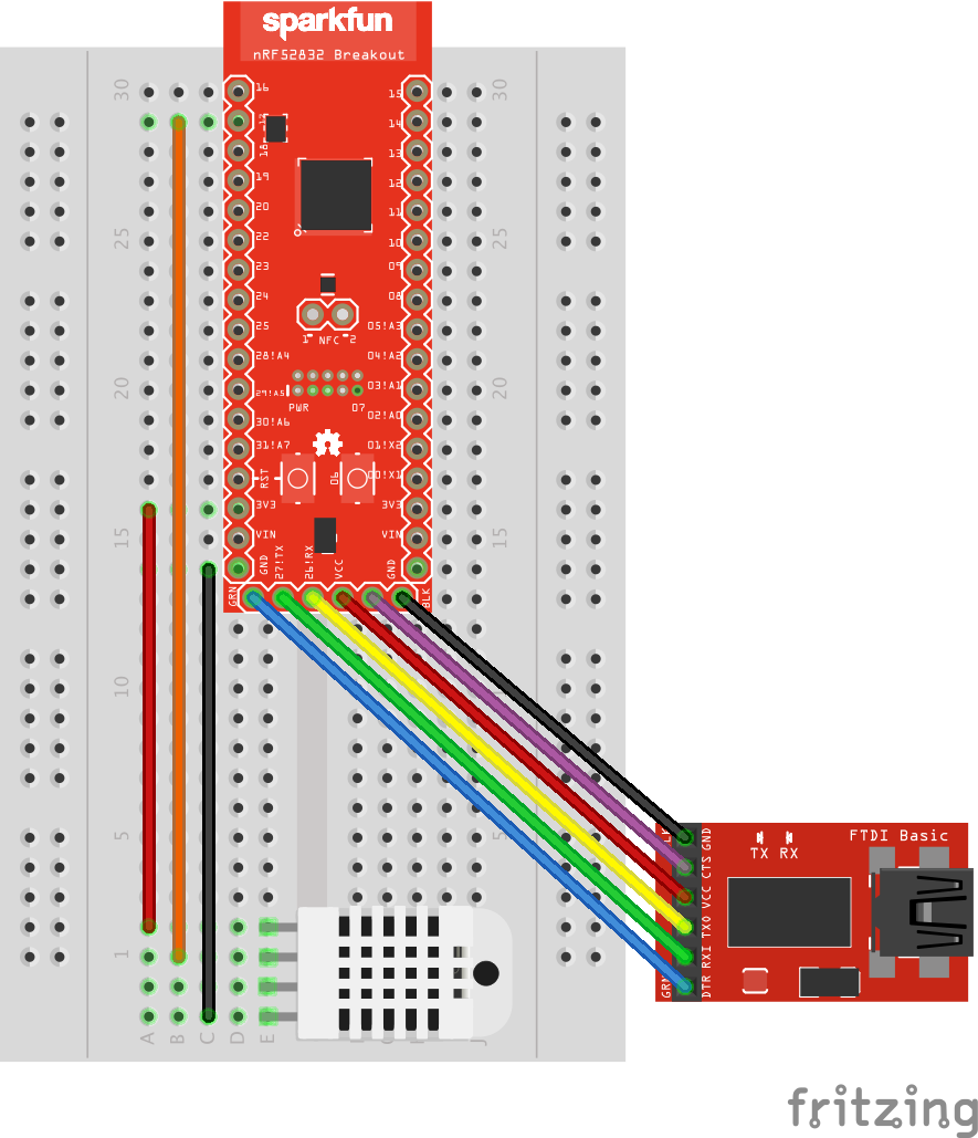
Assembly instructions
- Complete the procedure described in the WRL-13990 Hookup Guide (most importantly, solder the headers onto the WRL-13990).
- Insert the WRL-13990 into the breadboard as shown in the diagram.
- Insert the DHT-22 into the breadboard as shown in the diagram.
- Connect the DHT-22 to the WRL-13990 using 3 male-to-male jumper wires, as shown in the diagram.
- Connect the WRL-13990 to the USB-to-serial chip using the 6 female-to-female jumper wires, as explained in the Hookup Guide from step 1.
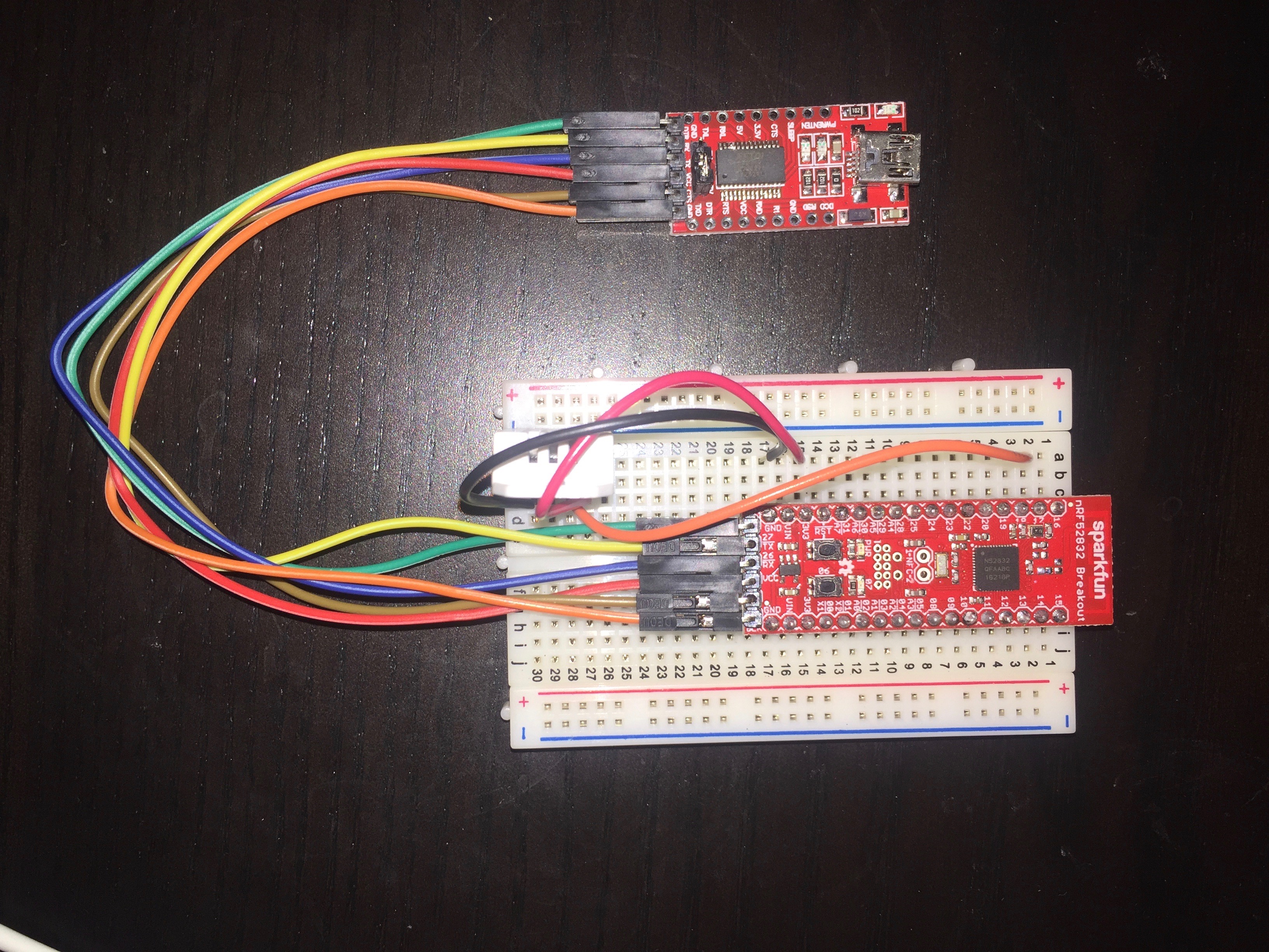
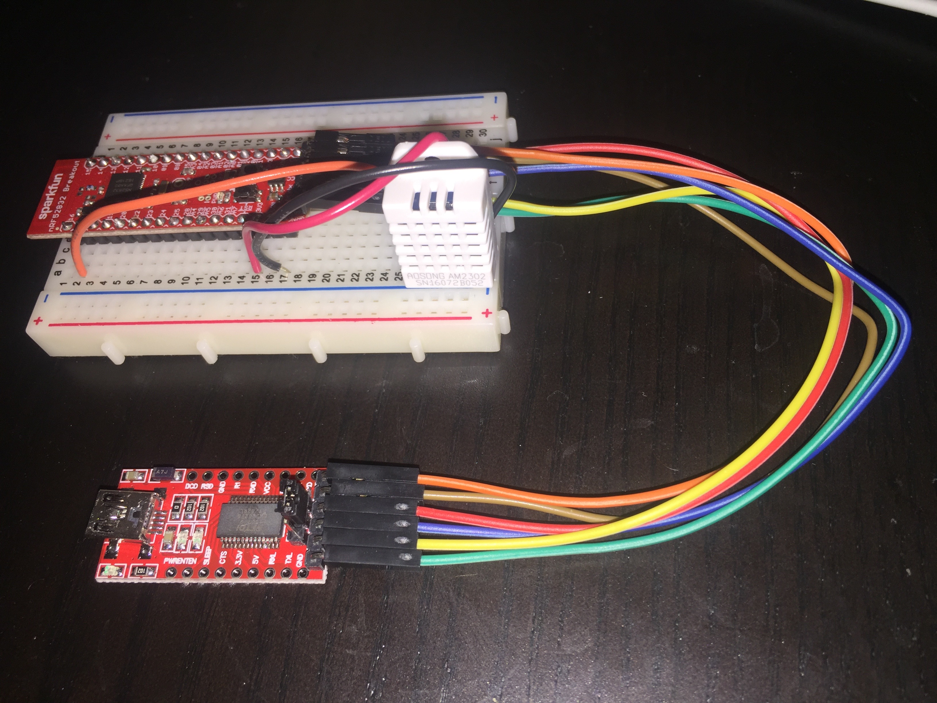
Photos
Once assembled, our sensor (with attached USB-to-serial programmer) looks like this:
Software architecture and data flow
Now that we’ve assembled the sensor, we need to program it. In the next post, we’ll look at the sensor’s software in detail. Here, let’s look at the required software functionality from a high level.
The basic data flow is as follows:
- The sensor periodically broadcasts its readings over BLE. (sensor module)
- The HAP bridge listens for the sensor’s BLE broadcasts, repeatedly storing the last received value. (bridge module)
- After receiving a new BLE broadcast, the HAP bridge broadcasts the new sensor reading value over HAP via Wi-Fi to paired HAP devices. (bridge module)
Sensor module
As discussed in the previous post, I aimed to keep the sensor’s role as simple as possible in order to achieve low power consumption (and thus long battery life). The “dumb” sensor’s only task is to indefinitely broadcast sensor readings out over BLE; all HAP functionality is offloaded to the bridge.
The sensor module will utilize Nordic’s nRF5 SDK to interface with the SoC hardware. It will also be necessary to interface with the DHT-22 in order to read measurements from it.
Bridge module
As explained in the previous post, the bridge will use HAP-NodeJS to abstract away the details of HAP communication, including device pairing and sensor value communication. The bridge will also utilize a node.js BLE library in order to receive BLE communications from the sensor.
Diagram
Here’s a block diagram showing our software architecture. Our custom-written modules are shown in white, while third party modules are shaded.
Conclusion and next steps
Now that we’ve looked at hardware assembly and high-level data flow, we’re ready to get into the software implementation details. In the next post, we’ll look at the software code necessary to make our sensor work.